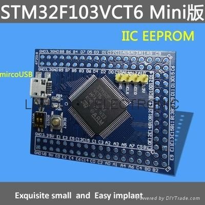
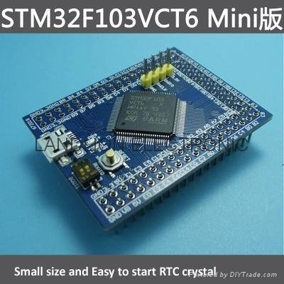
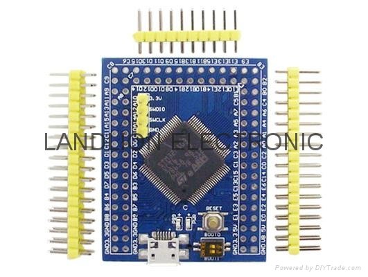
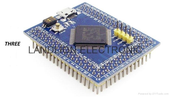
STM32F103VCT6 Mini minimum system
Product Description:
This is a ARM core board, is based on the main chip STM32F103VCT6 , has the following characteristics:
1, on board the most basic MCU-based circuits, such as crystal oscillator circuit, USB power management circuit and USB interface.
2, the core board leads to all the I / O port resources.
3, with SWD simulation debugging download interface, the interface requires at least three lines to complete the debugging download task, compared to the traditional JTAG debugging has a lot of benefits, here insert a, JTAG now big to eliminate the trend, For example, ST's new M0 series MCU only retains the SWD debug interface, JTAG directly canceled.
4, the use of the current smart phone used by the Mirco USB interface, easy to use, do USB communication and power supply.
5, the core board of the system crystal (8MHz) use high precision high quality and low load NDK's NX5032GA, without the use of low-cost iron crystal.
6, for the STM32 RTC can not afford the problem, we have adopted the official proposal of low-load RTC crystal program, and the use of the Epson brand crystal, and did not use cheap cylindrical crystal.
7, the core board with EEPROM, model AT24C08 convenient core board for data storage.
8, power regulator chip input and output, respectively, placed a large capacity of high-capacity tantalum capacitors, will be in the regulator, filter plays an extraordinary effect, the same we have not found on Taobao than we use the capacity The greater the value of the seller, heaven and earth conscience.
9, with a high quality 2.54mm spacing of the double row of pin, to ensure good contact with electrical conductivity, user-friendly core board will be placed on the standard million board or breadboard. Paier default welding, the user can choose according to their own needs welding direction.
Chip Introduction:
1, STM32F103VCT6
Package Type: LQFP;
Number of pins: 100;
Kernel: Cortex ™ -M3;
Operating frequency: 72MHz;
Storage Resources: 256K Byte Flash, 48KByte SRAM;
Interface resources: 3xSPI, 5xUSART, 2xI2C, 1xSDIO, 1xFSMC, 1xCAN, 80xI / O port;
Analog to digital conversion: 3x ADC (12 bits / 16 channels);
Digital-to-analog conversion: 1x DAC (12 bits);
Timer: 4 general timers 2 advanced timers;
Debug download: support JTAG / SWD interface debugging download, support IAP
2, RT9193-33: 3.3V regulator chip, the maximum 300mA current.
3, AT24C08: 1024Byte x8, high data transfer rate of 400KHz and IIC bus and
Capacity, the number of erase in about 100 million times, the data storage can be 100 years;
Introduction to interfaces:
1, SWD interface: support simulation, download and debugging.
2, Mirco USB interface: power supply and USB communication function, does not support the download.
3, USART1 interface: can be used for USART1 download program, or use USART1
To communicate.
4, MCU pin interface: lead all the I / O port pin, easy to connect with the peripherals.
5,5V and 3.3V power input and output interfaces: commonly used for external power supply, or with other modules
For co-processing
Other device introduction:
1, power LED (PWR): power indicator state, you can determine whether the power supply is stable.
2, user LED (PC13): easy to I / O output test or indicate the program running status.
3, start jump selection programming mode: (1, user flash 2, SRAM 3, system memory).
4, reset button: for the user to reset the chip program.
5,8M crystal: can be set by the frequency to make the system clocked at 72MHz.
6,32.768KHz Crystal: available for built-in RTC, or for calibration.
Distribution information:
1, keil ARM software MDK programming software
2, the core board program Demo (mainly core board test program)
3, the core board technical documentation (mainly related device technical manual)
4, the core board hardware information (mainly circuit diagram)
5, STM32 learning materials (technical manual and reference routines)
With suggestions:
STM32 series MCU now download the program usually use SWD mode and ISP mode: the store has its supporting debugging module, wiring and use is very convenient, it is recommended to buy. Respectively:
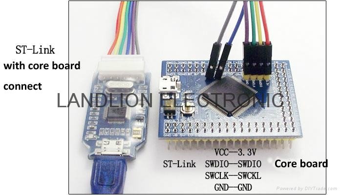
1, the use of SWD mode download, you need to use the debugger is J-Link or ST-Link
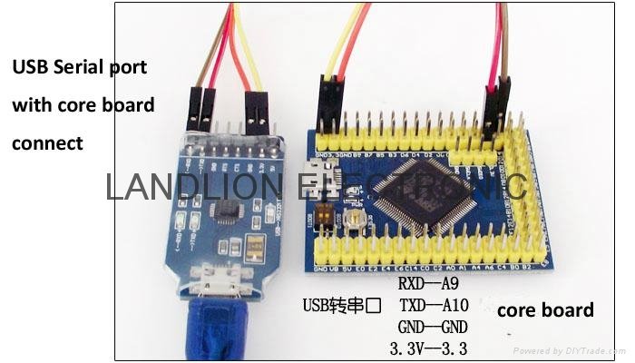
2, the use of ISP mode download, you need to use the USB to serial (TTL level)
note:
1, if the core board has been powered by other power modules, the USB to TTL module 3.3V pin does not need to connect with the core board 3.3, just connect the three DuPont line to avoid cross-powered;
2, in the download process, the need to set the BOOT pin to BOOT0 = 1; BOOT1 = 0, so that through the serial download program;
3, if you want to debug the serial port function, you do not need to set the BOOT level pin, according to the default settings can be.
4, under normal circumstances, ISP mode download SWD mode download a little more trouble, often used as a debugging serial port.
Precautions:
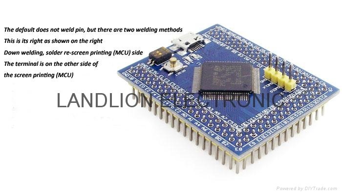
1, the core board factory has been rigorously tested, has been downloaded into a LED (PB9) light flashing program, the buyer on the board power supply, the board red light (power PWR) will always light, indicating the board hardware is normal, the core board factory Before the default does not weld pin, the user needs to solder pin, need to explain in advance.
2, the core board to provide some low-cost sales technical support. Provide test procedures, related learning materials and software, provide pdf format schematics (the above information are sent or online transmission, do not send CD). This product can not be called a learning board, can be called a development board or core board, just as a developer to improve the speed of development purposes. OUR small profits, before the hair will do the appearance of detection, programming testing, simulation connection detection.
Shipping list:
1, STM32F103VCT6 core board 1
2,2 * 18 2.54mm pitch pin 2 2 * 10 2.54mm pitch pin 1
3, supporting learning materials: through the network disk download and forum download